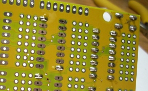
Analog Shield Build Instructions
It shouldn't take more than an hour to get your Analog Shield assembled and ready to accept inputs. This is a soldering project, so you should know how to do that first.
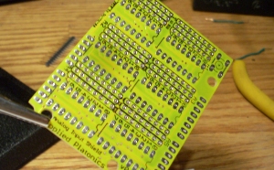
Install the reset button (optional)
If you really, really need to have a reset button, you can
solder it in first. Insert it the way it fits, and solder.
But, do you really need it? They're great for development, but
awful for deployment.
Install your IC sockets. Place them on the top (the
side with the silkscreen), with the notch up, and solder
down. On each socket, solder down opposite corners
first, to ensure it can't get loose while you're
working. After that, fill in the other pads.
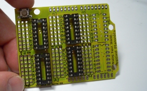
Mo sockets mo multiplexed analog inputs
After you've soldered down the first socket, continue on to the other five.
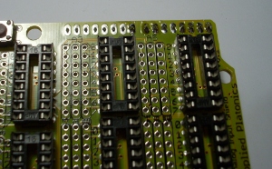
Solder down the header pins
Once all the sockets are in place, solder down the header
pins. You'll need to break them apart; a pair of wirecutters
does the job nicely. You'll want two 6-long sets, and two
8-long sets. Your kit came with either a 28-long row or a 16
and a 12. (There may be extra, depending on how magnaminous I
was feeling the day I packaged your kit.)
It's best to tack down one end of the pins, then straighten them up, then solder down the rest. Careful not to touch the pin you're soldering, though
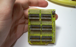
Ready to receive our multiplex chips
Next, plug in all your 4051s. Make sure the notches are all
on the digital pin side of the board. Notches: very important!
("Notches for show," hah-hah)
The pins should be a little too wide; that's how you know they're fresh (seriously, why does everyone sell their chips with the pins flared out?). Flatten them by lying them on their side, holding them by the ends of the plastic, and rolling them ever so gently into the table.
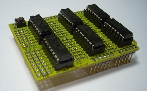
Socket the 4051s
Do the 4051 leads fit into the sockets now? If you overdid
it, very gently pull them back with the pad of your fingertip.
Using your fingernail works, too, but I've had too many IC
manicures go wrong to recommend that.
Once the leads fit, plug the chips in, with all the notches upwards. Double-check that they're in the right direction, and you're good to go!
Things to check:
- Are the chips' notches all pointing up, towards the digital pins?
- Are all your chips in the same direction?
- Are all the pins actually in their sockets? Make sure they didn't curl up under the chip
- Check for obvious shorts with a multimeter: the +5V line to Ground, 3.3V to GND, etc
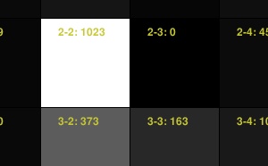
Test your readings
Check out the source code from the repo. Once you've got
that, load the analog_shield_daq Arduino sketch onto your
Arduino, and the analog_shield_grid Processing sketch. You
should be able to jumper individual input pads to +5V and GND to
toggle them between 1023 and 0, or add sensors to your heart's
content.
Congratulations!
Congratulations! You just assembled your Analog Input Shield! Attach your sensors, connect your logging device or music rig or whatever, and take a cameraphone pic!
