Breaduino Build Instructions
It shouldn't take more than an hour to get your Breaduino working, even with a few mishaps. To speed things up, begin by gathering up the required supplies and tools. Once you've done that, you'll soon have built your very own Arduino clone!
Build the Breaduino
Got it all? Great! Let's build a Breaduino! This should go pretty quickly, but, take your time, and make sure to test each step as you go along. We'll do this in two "subsystems": the power supply and the Atmega328.
Build the power supply
We're going to start by building the power supply. The power supply takes the output of your power source (wallwart/9V battery), and turns it into 5 volts DC. The Breaduino's internal components can only run on 5V; if they were fed 9V, they would fail.

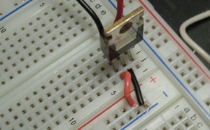
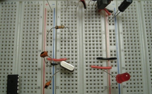
Start out by plugging in the 7805 at the top of the board, as shown in this picture. Make sure the metal tab is facing out to the right. We'll put it on the first row, at the far right.
Next, add input power leads. Ground connects to the center pin, and the input voltage on pin 1. Make sure to use black wire for all your ground connections, and red for your positive power connections. You'll appreciate it later.
Things to check:

Connect power
Now, hook up power to your 7805. I'm using alligator clips to connect to the ends of my wallwart's cord. Make sure to connect ground to the black cord, and positive voltage to the wire you put in pin 1. You may want to triple-check the polarity of your power supply before attaching the leads.

Check output voltage is +5V
Now, check that your 7805 is giving out 5V on the third pin.
Things to check:
- +5VDC from the tab to pin 3
- +5VDC from pin 2 to pin 3
Connect the busses
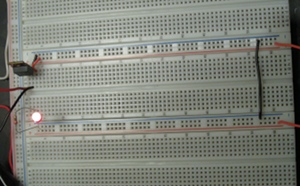
Next, we connect ground and +5V to our power busses along the side of the breadboard. Connect the right power busses as shown here, then run jumpers over to the left side of the board as shown in the next step.
Connect the left (err, bottom) busses, too
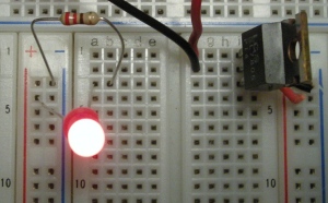
Once both busses are connected up, we'll make sure the connections are good by putting an LED from 5V to ground. It should light up, showing that things are connected correctly
LEDs have one leg that's slightly longer than the other. The longer one should go towards the positive side, while the shorter leg should go towards ground. Put the longer leg in +5V on the left side bus, and the other in the left side of row 3. LEDs need to have a resistor attached to them, so put one of the 220Ω resistors between the left hand ground and row 3, as shown in the picture below.
Things to check:
The LED should light up (it will only light up if power is connected to the left hand power busses). If it lights up, go on to the next step. If it doesn't, try flipping it around; you might have it backwards. If it still doesn't light up, measure the voltage between the positive and negative bus on the left hand side. This should be +5VDC. If it's not, check that your 7805 is putting out 5V on pin 3. If that's working, but there's no light, it's a wiring problem between your power busses. If the 7805 isn't giving out 5V, check your input voltage. If it's between 7VDC and 12VDC, check to make sure it's positive and not negative: if it's negative, you might have fried your 7805. If it's positive and over 12V, you might also have fried your 7805. If it looks right, but nothing's happening, you may have a short; check the connections in your breadboard, and make sure wires aren't accidentally touching anywhere.
Check that the left busses have power
It's a little hard to see in this picture, so here's a
textual description of the connections here:
LED: long leg
in +, short leg in 3a.
220 ohm resistor: one leg in 3b, the
other in -.

Now that the left power bus is known-good, move the LED so its cathode (the short leg) is still connected to the 200 ohm resistor, and connect its anode (long leg) to the 7805's +5V output (pin 3).
Things to check:
The LED should light back up. If it doesn't, follow the diagnostic steps in the last Things To Check block.

Add filter capacitors
To help smooth out the power supply, add the filter capacitors. There are two 10�F capacitors in the kit. These bigger capacitors have long and short legs like the LEDs, and the mean the same thing: long legs go to positive, short legs go towards ground.
Install one of the 10�F capacitors between your input voltage and ground (7805 pin 1 and pin 2, with the short lead on pin 2), and the other capacitor between +5VDC and ground (I like to put mine on the power bus, as shown in this photo).
Things to check:
The power indicator LED should stay lit. If it goes out, remove the capacitors, and see if it comes back on. If it comes back on after removing the capacitors, there's a problem with either the capacitors or their installation. Double-check how you're installing the capacitors, and try it again. If it goes out again, you may have a bad capacitor. If you suspect it's a bad capacitor and you have a friend who knows about electronics, see if they can help you narrow it down. If you have a bad capacitor, let me first apologize! Sorry for the inconvenience; email me, and I will mail you a new pair of caps.
Wire up the Atmega328

Now, put the Atmega328 on the board where it's going to live. We'll put it with its first pin at row 11. Note that there's a notch on one end of the chip; this is pin 1. Don't plug it in all the way, this is just a dry-fitting, to make sure you can drop it in where you want to, without anything else interfering with the connections.
Make a note of where the first pin goes, and how far down the bottom of the chip goes. In these instructions, the first in is in row 11 and the last one in row 24.

Remove the Atmega328 and put it aside. Install power connections as seen to the left. The connections are also given in coordinate form below.
Things to check:
- +5V from the left + bus to 17c (Atmega pin 7)
- Ground from the left - bus to 18c (Atmega328 pin 8)
- +5V from the right + bus to 19g (Atmega328 pin 20)
- Ground from the right - bus to 17h (Atmega328 pin 22)
The power indicator light should stay on. If it is on, go to the next step. If your power LED is off, you have either knocked a power wire loose or caused a short someplace. Use your multimeter to check if the 7805 is outputting 5V.
If the 7805 isn't outputting 5V, check your input voltage. If you have good voltage coming in, but no voltage coming out, your 7805 is either loose or fried. Be careful: these things often get really hot when they fail. With that in mind, cup your hand a few inches above the 7805 to see if it's hot. If it's not incredibly hot, try wiggling it in its socket.
If the 7805 is outputting 5V, unplug your power and look closely at the connections you just made. Somewhere, you have metal plugged into +5VDC touching metal plugged into ground. It might not be obvious, but it's there. If it's not obvious, try unplugging the four wires you just put in, and turn power back on. If the light comes back on, try this step again. If the light still doesn't come on, but there is 5V coming out of the 7805, there's a short in the rest of your circuit. Disconnect power again, and look closely at the rest of it. The filter caps have really long leads, which sometimes get twisted into each other. The worst case scenario here is that you have to gradually unplug components, trying power each time, and have to rebuild the circuit.

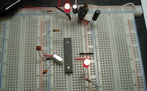
All Arduinos and (good) clones have an LED built in on pin 13. The Breaduino, being a great clone, has one, too. We'll install that, now. Digital 13 is pin 19 on the Atmega328, which is on the right hand side of row 21 on our board. There's another LED in the kit, and another 220Ω resistor. Connect the long leg of the LED into row 21, and the short leg of it into something down past the end of the Atmega328. Here, I'm using row 26. Then, connect the 220Ω resistor between that row and the right hand ground bus.
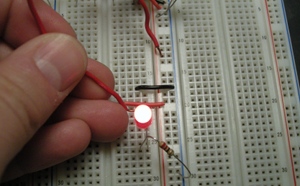
To check the installation of the LED for digital 13, connect a long bit of wire to the positive bus, and touch it to the long leg of the LED, as shown. If everything is installed correctly, it will light up.

If the LED doesn't light up, check that the resistor and LED are connected, and that the resistor is connected to ground. If both of those are true, you might have installed the LED backwards. Flip it around, and try again. If it still doesn't light up, it may be that the LED is bad. Try swapping it in for the power indicator LED, and see if it works up there. If the power indicator LED is lit but this one doesn't light up when you swap it in, and the other LED is on when you swap it back in, you've got a bad LED. Drop me an email, and I'll send you a new one. Sorry about that!

Now, install the crystal and its 22pF capacitors. The crystal is what keeps the Atmega328 going, kind of like the guy who shouts "Stroke!" to keep the paddlers in a boat in time. The Atmega328 wants its crystal installed between pins 9 and 10, with the little 22pF capacitors going to ground from each of them. If this picture isn't helpful, check the next one; if it still isn't clear, a checklist is found below. Note that these little caps don't have a long/short lead, and don't care which direction they're hooked up.
Install the pull-up resistor (10k)
Almost there! Install the 10k ohm resistor between the left + and pin 1 of the Atmega328. That's row 11; I have it on 11d here. This is a pull-up resistor, to keep the Atmega328 from randomly resetting itself.
We're at the final step! You're about to install the Atmega328, which will complete your very own, handcrafted Breaduino! Time for our second-to-last checklist.
Things to check:
- Is the power indicator light still on? Is power connected? If power's connected, but the light isn't on, check for a short as described above.
- Are your Atmega328 power connections in the right place? Have you double checked? There's a handy list of the Atmega328 connections above, if you want to double-check now.
- Is the LED on digital 13 working? If not, try the troubleshooting listed in its step.
- Using your multimeter, make sure there's +5V on the row 11 side of the resistor
Once all that's done, disconnect power, and wait for the LEDs to fade all the way out. Once that's done, we're ready to plug in the Atmega328!
Final pre-flight check! Plug the Atmega328 into your un-powered board, with pin 1 in row 11. Is the little divot in the top of the chip on row 11? Does it look like the picture to the left? You should have the 10k resistor connected to pin 1, then five empty pins, then positive, then ground. Is that all correct? Do you have a ground line on the right side of the chip, directly opposite the positive one? Is there a positive line one hole below that? Awesome, you're ready!
Once you've double-checked you're not about to fry the chip, connect power, and watch your blinky light go!
Congratulations!
Congratulations! You just built your own Breaduino! The next step is adding a serial port to it, so you can reprogram it with the serial cable in-place. That said, you don't really need to: you can swap this chip into your Duemilanove, Boarduino, or other Atmega328-based Arduino clone, and program it there. After you're happy with it there, put it back into your breadboard and voila, it's working again.
